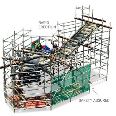
Mobile scaffold towers erected to heights exceeding 12 meters enter a wind-loading regime fundamentally different from the ground-level conditions for which standard stability calculations are performed. Wind speed increases with height according to a power-law profile, and the tower structure itself presents a sail area that generates overturning moments proportional to the square of wind velocity. A standard 0.75m-wide tower at 20-meter working height in a 15 m/s wind (Beaufort Force 4, described as "moderate breeze") experiences an overturning moment approximately 8 times greater than the same tower at 4-meter height. Without engineered mitigation, this wind-induced moment can exceed the tower's self-weight restoring moment, creating an overturning hazard even under wind conditions that feel unremarkable to workers at ground level.
Engineered Mitigation: Footprint Expansion PhysicsThe Wide Base Outrigger system addresses wind stability through geometric rather than mass-based means. By extending the effective base width from 0.75m to 2.5m per side (5.0m total base width), the resisting moment arm increases by a factor of 6.7. Since overturning resistance is the product of tower weight and the horizontal distance from the pivot point to the center of gravity, this geometric expansion achieves the same stability enhancement as adding 4.5 tonnes of ballast weight—without the mobility penalty that ballast imposes. Each outrigger beam telescopes independently through a threaded screw mechanism with intermediate lock positions at 0.5m increments, enabling graded stability selection based on the specific working height and wind forecast for each deployment. A setup placard correlates working height with minimum required outrigger extension for wind conditions up to 12.5 m/s (the maximum wind speed for safe tower use per EN1004), removing the need for on-site engineering calculations.
Hazard Mitigation for Soft Ground: The articulating ball-and-socket outrigger feet address a secondary failure mode where standard flat stabilizer pads on soft or uneven ground develop edge loading that progressively sinks the pad edge, creating a self-reinforcing tilt cycle that can progress to overturning even in zero-wind conditions. The 250mm diameter load-distribution plates with 15-degree swivel articulation maintain full surface contact regardless of ground inclination, distributing the outrigger reaction force over 0.049 square meters per foot. On ground with a bearing capacity of 100 kPa (typical of compacted construction site fill), this provides 4.9 kN of support per foot—sufficient for the full outrigger reaction force at maximum extension and load.
Key Features| Parameter | Specification |
|---|---|
| Outrigger Extension (Each) | 0-2.5m from Centerline |
| Intermediate Lock Positions | Every 0.5m |
| Maximum Working Height | 24m |
| Platform Dimensions | 2.0m x 0.6m |
| Material Grade | Aluminum Alloy 6082-T6 |
| Outrigger Beam | Rectangular Box + Internal Webs |
| Foot Plate Diameter | 250mm |
| Foot Articulation | Ball-Socket (15 deg) |
| Pivot Mount | Double-Shear 8x M12 SS |
| Tube Wall Thickness | 3.2mm |
| Load Capacity | 200 kg/sqm |
| Outrigger Weight | 35 kg |
| Surface Treatment | Anodized Silver |
| Wheel | 250mm Heavy-Duty Lockable |
| Standards | EN1004:2004, EN12810 |
Outrigger beams pre-installed in stowed position within base frame channels. Calibrated torque wrench included for M12 pivot fasteners with placard-specified values. Custom steel stillage packaging. 36-month structural warranty with annual re-certification inspection service available for rental fleets.